SIMPLIFIED DESIGNING with AutoDesign:
FAST START
for

Running the program:
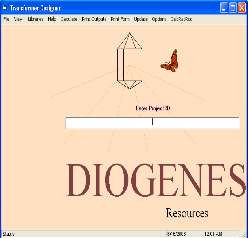
When the main Transformer Designer screen appears, Select FILE, then AUTODESIGN.
The window can be maximized to utilize the entire screen.
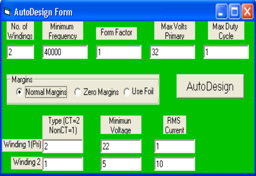
When the AutoDesign form opens, enter the required data as in the following example:
Enter the number of windings (2 to 8)
Enter the minimum operating frequency in Hertz
Enter the form factor (1.11 for a sine wave, 1 for a square wave, etc.)
Enter the maximum expected primary RMS voltage
Enter the duty cycle in per unit (Usually 1, but less for pulse width modulation)
The program uses the margins stored with the conductors unless the “Use Foil” or Zero Margins radio button is selected. If “Use Foil” is selected, the program calculates foil parameters to fit the core.
Enter the winding type for each of the windings (2 for center-tapped, 1 for not center-tapped)
Enter minimum RMS voltages for each winding
Enter RMS currents for each winding. It is not necessary to enter a current for the first or primary winding - the program calculates it.
Click on AutoDesign. (If “No Dongle Installed” error occurs, see “Installing the Security Device” above.) The program completely designs the transformer and, when finished, displays the output results. The rest of the forms can be displayed by clicking on VIEW then VIEW ALL FORMS:
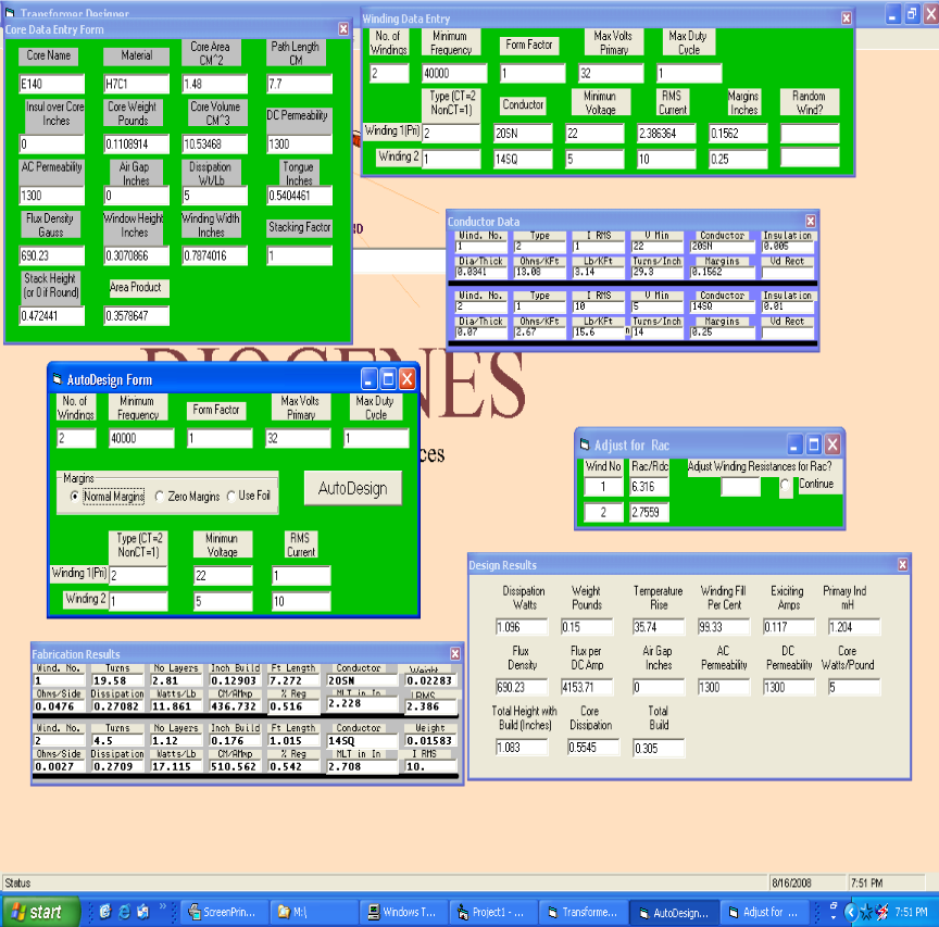
The “AutoDesign” form can be added to the display from the bottom minimized bar. The forms with green background are input forms which, in AutoDesign mode are filled out by the program. The forms with grey background are output forms. The “Design Results” form contains information which the designer can use to determine if the design is optimum. The “Fabrication Results” form contains information the shop can use in the production process.
Note that almost everything thus far can be understood by someone who has little or no magnetics knowledge. Almost everything is in circuit design terms. The neophyte should read Important.doc on the CD which explains a few terms. At the end of TrDsMan4.doc the parameters used by the program a re listed and described.
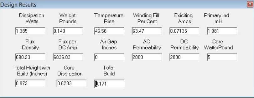
This Design Results form shows information the designer can review to be assured that
all his concerns have been adequately addressed. This data can also be printed by
Print Outputs\Design Data.
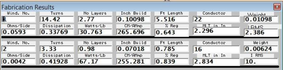
The Fabrication Results form shows data needed by the shop to fabricate the transformer.
This data can also be printed by Print Outputs\Fab Data.
The remaining 3 forms can also be displayed.
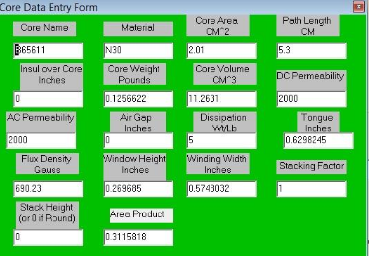
The Core Data Entry form contains all the relevant data on the selected core, including
both the electrical and physical parameters.
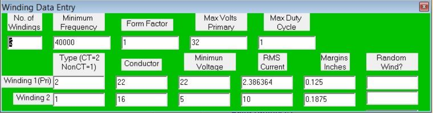
The Winding Data Entry form contains most of the data entered by the designer plus the selected conductors.
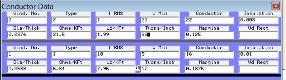
The Conductor Data form includes the data parameters for each conductor
from the Conductor Library.
The output data can be selectively printed in two collections. The two printouts available under Print Outputs are illustrated as:
| TOTAL WATTS | CORE WEIGHT | TEMP RISE | % FILL | MAG CURRENT | PRIMARY INDUCTANCE |
|---|---|---|---|---|---|
| 1.385 | 0.143 | 45.56 | 63.47 | 0.07135 | 1.981 |
| FLUX DENSITY | FLUX PER DC A,MP | AIR GAP | AC PERM | DC PER | CORE WATTS/LB |
| 690 | 6836 | 0 | 2000 | 2000 | 5 |
| TOTAL HEIGHT | CORE WATTS | FLUX/PER DC AMP | TOTAL BUILD | ||
| 0.972 | 0.6283 | 6836.03 | 0.171 |
The Design Outputs printout contains data useful to the designer to determine if the design requirements have been adequately met. This is the same data as in the Design Results form.
FABRICATION DATA
| WIND NO OHMS/SIDE | TURNS WATTS | LAYERS WATTS/LB | BUILD CM/AMP | LENGTH %REG | CONDUCTOR MLT (IN) | WEIGHT IRMS |
|---|---|---|---|---|---|---|
| 1 | 14.42 | 2.77 | 0.10098 | 5.516 | 22 | 0.01098 |
| 0.0593 | 0.33769 | 30.763 | 265.696 | 0.643 | 2.296 | 2.386 |
| 2 | 3.33 | 0.98 | 0.07018 | 0.785 | 16 | 0.00624 |
| 0.0042 | 0.41928 | 67.17 | 255.281 | 0.839 | 2.834 |
The Fabrication Data printout shows data needed by the shop to fabricate the
transformer. This is the same data as is available in the Fabrication Results form.
The design can now be:
1. Sent to the shop for fabrication.
2. Saved for future reference.
3. Modified using the manual design techniques described in the online manual,
and recalculated.
4. Printed. In addition to the above described printouts, any of the design forms
can be printed.
If this project is saved now, all the input forms and data are saved. Running “Calculaate
now will reconstruct all the forms.
Calculations use the maximum temperature rise of 50 degrees centigrade
by default. A different temperature rise can be entered under “Options” on the main menu.
High Frequency Effects
Initially, calculations are made without regard to the increase in resistance due to operating frequency.
The “Adjust for Rac” form shows the estimated ratio of AC resistance to DC resistance
because of skin depth and proximity effects. If it is desirable to recalculate the transformer
using the higher AC resistances, answer “Yes” and select “Continue”. Any subsequent
calculation will include the AC resistance values.
Answer Yes or Y or y and click continue. Calculate and and View All
Forms. The temperature rise using AC resistance is large in this case (about 94 degC).
This may not be acceptable for whatever reason. Sometimes there is an actual
limit specified. One method to mitigate this rise is to initially design for lower
temperature rise. Select “Options” on the top menu bar then “Temperature Limit”.
Then change the temperature limit to a lower value, say 30degC. After recalculation using
the same AutoDesign form and recalculating with AC resistance, the resulting temperature rise
is about 53degC – a great improvement in this instance. However the selected core has
changed from B65611 to PQ35/35 and the weight has increased from 0.143 to 0.246.
Another method is to keep the 50degC limit and use the same Auto
Design form but with “Use Foil” selected. This results in a temperature
rise after correction for AC resistance of only about 48 degC. Also note that the core
selected is now 3622-L00-3C8 and the weight has increased from 0.143 to 0.193. If the
AC resistance presents a problem, a recalculation using foil conductor is usually
quite effective in reducing the ratio of Rac to Rdc.
Note that the only requirement was to select Use Foil – the program
selected the foil size, calculated the electrical parameters, and used them to
design the transformer. Using manual design, the designer has the option of picking
the foil, but the program can be utilized the calculate the parameters.
| Transformer Core | Conductor | Design Temperature | Temperature DC Rise | Temperature AC Rise | Weight |
|---|---|---|---|---|---|
| B65611 | Wire | 50 degC | 46.56 degC | 93.72 degC | 0.144LB |
| PQ35/35 | Wire | 30 | 24.31 | 53.0 | 0.245 |
| 3622-L00-3C8 | Foil | 50 | 42.76 | 48.26 | 0.193 |
Core Air Gap
An air gap in the core has at least two effects. First, it can mitigate the effects of any unbalance in the circuit, making at least some gap desirable and a gap will alleviate some of the effects of a core cracking or powdering. However, a gap also lowers the primary inductance, which increases the magnetizing current. Of course, the program calculates these parameters. In the first design described above, with zero air gap, the primary magnetizing inductance was calculated as 1.987 mH, resulting in an input magnetizing current of 0.07135 Amps. Compared to the primary load winding of 2.386 amps the magnetizing current is less than 3% with zero air gap. With a 2 mil gap, the primary inductance rises to 679 mH with an exciting current of 0.208 amps, still less than 9% of the input current. Of course, the two currents are in quadrature and therefor add vectorally, not arithmetically. The old rule of thumb for low frequency transformers was not to exceed about 30% of the input load current.
Possibly you are not entirely satisfied with the design. Maybe you don’t have an E140 core with H7C1 material on the shelf. Or your shop’s winding practices can’t meet the winding fill requirement (this calculation includes a 5% bulge factor). You can modify anything in the input forms and recalculate manually. Manual design is very flexible, allowing use of any core and any conductor. The Cores Library and Conductor Library can alleviate most of the dog work of entering data.
AutoInductor
Refer
to AutoInductor Demo on this Website
Manual Design:
This program has been designed to be highly flexible, and there are a
multitude of possibilities in manual mode. It is possible to start a new
design or to open a saved design for modification. Entering data can be
manual or the core and conductor libraries can be utilized to reduce the
effort considerably. (The libraries are not required, however they can
simplify the process markedly.) The familiarization routine in the manual
should be helpful in pointing out the possibilities. The manual for
Transformer Designer is on the CD as a Microsoft Word document under TrDsMan4.doc.
Sample Designs:
To illustrate some of the flexibility of the program, several sample designs are included
on the CD in the Nsamples directory (files with the .dio extension). Most of these designs
are not optimum and are offered only as examples.
This document is available on the TRANSFORMER DESIGNER CD under TrDsV4FastStart.doc
See the manual
on the
TRANSFORMER DESIGNER CD under TrDsMan4.doc for AutoInductor and other topics.
Note:
If you are new to magnetics design, you may want to peruse Important.doc for some useful data.
For some ideas on how to control the increase in Rac at high frequencies, check out HighFreqArtC.pdf
For general interest, you may find BiasedInductorArticle.pdf interesting.
For problems call 714-262-8488
William Blodgett